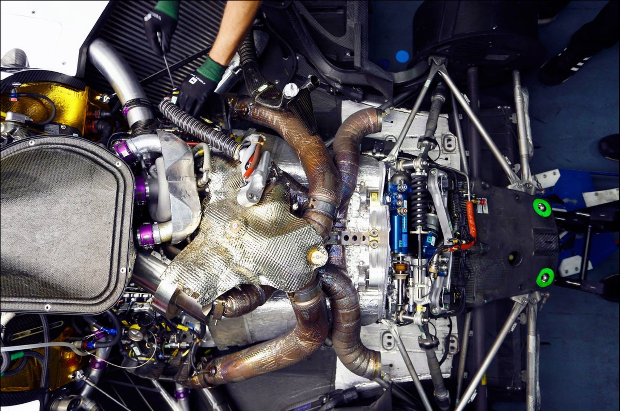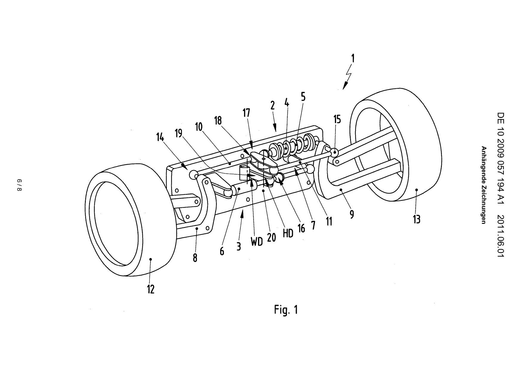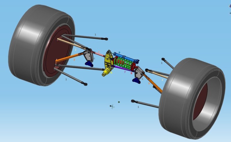
Part #1 (dark gray) is the lower and upper wishbones, part #2 (pale brown) is the tie rod, parts #3 (orange) are two pushrods and part #4 (gray) are two rocker arms. The pushrods move the rocker arms, which rotate around blue brackets attached to the chassis. When moved, the rocker arms activate a mechanism that operates on a principle very similar to that described in the patent. Specifically, one rocker arm is connected to a rod (part #5, pink), and the other to a spring damper for the tie rod (part #8, red) and to a second rod (part #7, purple).
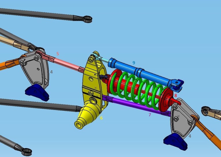
The central components of the layout in more detail.
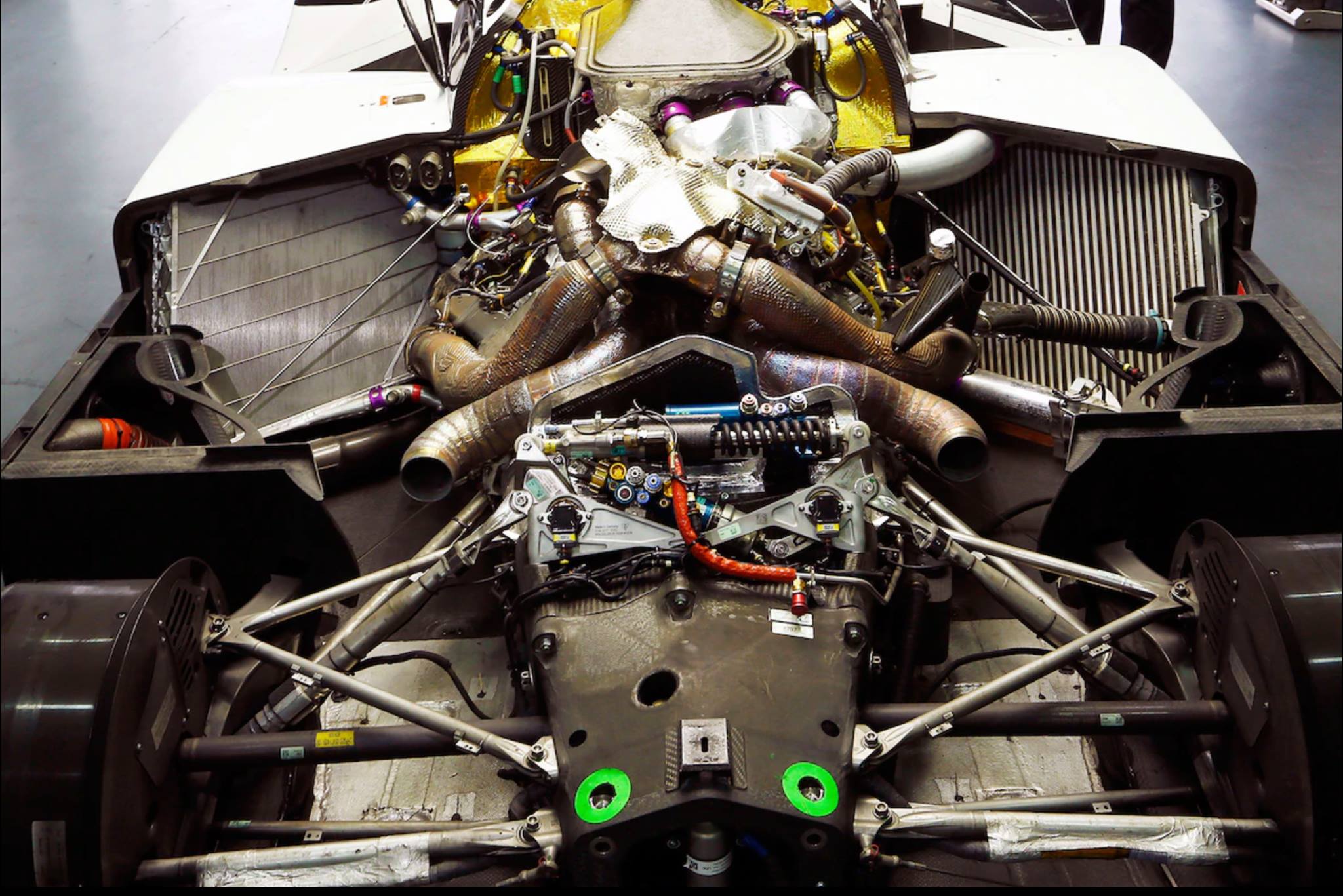
The main element here is the central link (part #6, yellow), which rotates around an axis attached to the chassis (the protrusion at its bottom), most likely activating a coaxial spring that acts as a stabilizer. The upper end of the link is directly connected to the torsion damper (part #9, light blue).
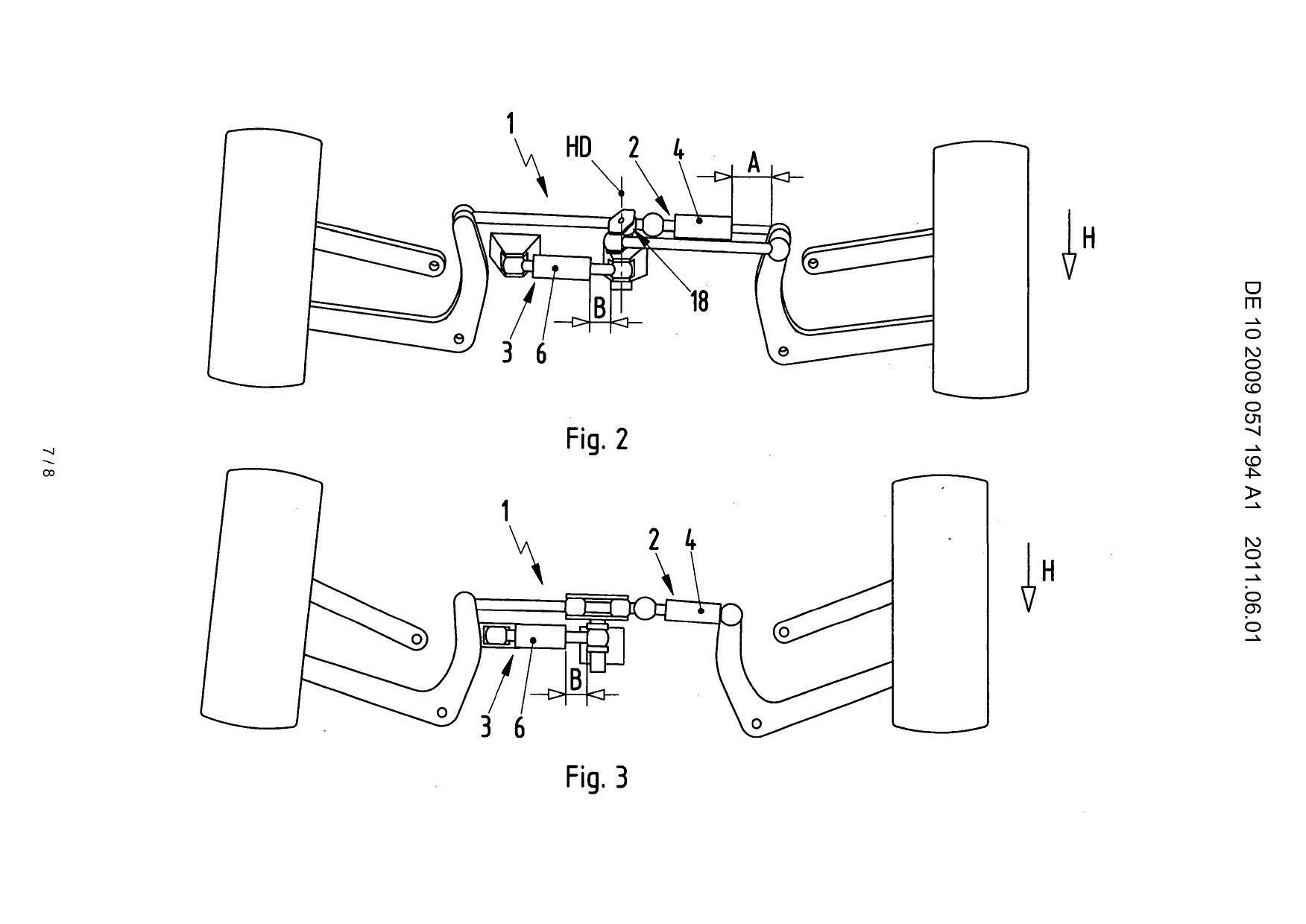
As in the patent diagram, the central link is not directly activated by the rockers and side rods. The latter are actually connected to a central lever, functionally very similar to the Watt mechanism seen in the patent diagram. This is better seen in the following picture, where the yellow central link has been removed for clarity to make the internal components visible.
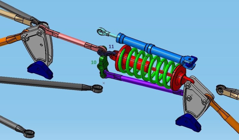
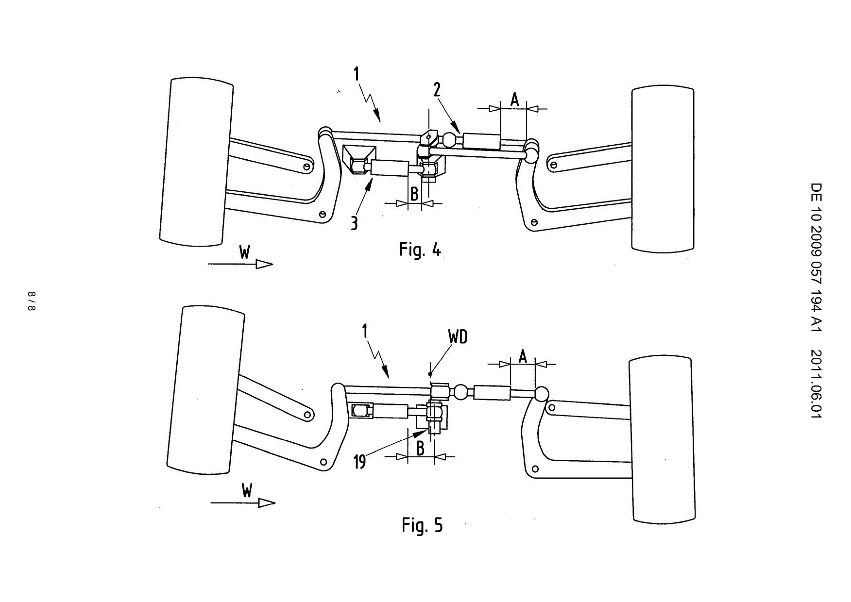
Both the pink (item #5) and purple (item #7) piston rods activate a center rocker (item #10, dark green) which is free to rotate around a pivot pin attached to the center rocker. This rocker is also connected at the top to a short arm (item #11, dark purple) which then activates the other side of the spring shock absorber assembly (item #5, red). The design of the short arm (item #11) and center arm (item #10) is just a sketch to show how each component is activated and does not in any way represent a working design.
It is clear that these parts will need to be designed differently to ensure proper rigidity and strength of the structure. This can be achieved, for example, by using a ball joint between part #5 and part #10 and an axial bearing between part #10 and part #11.
It should therefore be noted that this 3D model shown in the photographs only helps to explain how the kinematics of the proprietary Porsche suspension works.